I’ve been reflecting on my career recently, and one thing that stands out is that I wouldn’t be where I am today without the CWNP certifications—and the amazing community that’s grown around them.
Certifications have always played a key role in my professional journey. Even today, a large part of my time is spent taking, building, and teaching certification programs. But CWNP holds a special place in my heart.
Back in 2002, while studying for my CWNA, I fell in love with Wi-Fi. It might sound strange, but studying for that exam genuinely changed the direction of my life. I discovered this technology that felt almost magical. I was like a kid with a new toy—I just wanted to tell everyone about it. (Some things don’t change!)
I remember the comments I got at the time: “Wi-Fi will never replace wired networks” and “There’s no money in Wi-Fi.” But those opinions didn’t matter to me—I was completely hooked.
Looking back now, I realize it wasn’t just the technology I loved. A big part of it was the CWNA certification itself. It was created by a company called Planet3 Wireless (later renamed CWNP), and what made it so unique was that it was vendor-neutral. It didn’t focus on any one product—it focused on the technology itself, diving deep into how it all worked.
I’ve always been a detail-oriented person. As a kid, I was the one constantly taking things apart with a screwdriver just to understand how they worked (and occasionally attempting to put them back together—much to my mother’s dismay). The CWNA took that same approach: it wasn’t just about how to configure or manage Wi-Fi—it was about why it works the way it does. And I loved that.
Years later, at a CWNE roundtable event in Atlanta, I met Devin Akin—one of the founders of CWNP and the author of the original CWNA. Meeting Devin made it clear why CWNA resonated with me so much. Before then, I don’t think I’d met anyone quite as detail-obsessed as I was. We had conversations that I couldn’t have with anyone else I knew at the time. Maybe we were just two slightly strange, oddly similar individuals who had finally found each other.
But it didn’t stop there. Through CWNP, I met more people like us: Ben Miller, David Coleman, Keith Parsons, Kimberly Graves, Chris Hyde, Tom Carpenter—just to name a few. I had found my people.
Over the last 20 years, the wireless and CWNP communities have only grown. We’re not alone—there are so many of us who share this passion for wireless technology and a deep desire to truly understand it. Events like WLPC, Tech Field Day, and Wi-Fi Congress have brought us together even more.
CWNP is more than just a certification company. It’s been the foundation of a community. It’s connected me with people I’ve learned so much from—people I now consider close friends.
For years, Cisco Meraki has been celebrated for its intuitive, cloud-based dashboard that simplifies Wi-Fi management. Its ease of use has made it a go-to choice for small to mid-sized organizations. But what about large enterprises, universities, and high-density environments?
Meraki has gradually evolved to meet the needs of the enterprise space—first by integrating Cisco Catalyst access points into the Meraki dashboard. However, until recently, Meraki’s controllerless, cloud-based architecture presented significant challenges for large-scale campus deployments.
The Challenge with Controllerless Deployments
In a traditional Meraki setup, access points (APs) handle the placement of user traffic onto the network. This design requires all user VLANs to be trunked to each AP, which introduces two major issues in large deployments:
Wired Network Redesign Many enterprise and campus wireless networks rely on centralized data forwarding. In these setups, user traffic is tunnelled back to a wireless controller, meaning VLANs only exist at the controller—not at the edge. Extending these VLANs to every AP can be costly and complex.
Roaming Overhead In controllerless deployments, user roaming requires frequent switch updates to redirect traffic to the new AP. In high-density environments with thousands of roaming users, this can overwhelm the network and cause congestion.
Introducing the Campus Gateway
At Mobility Field Day 13 (MFD13), Cisco Meraki unveiled the Campus Gateway. This solution directly addresses the limitations of controllerless deployments in large-scale environments.
Preserve Existing Infrastructure Replacing a traditional controller-based solution with Meraki no longer requires a complete wired network redesign. The Campus Gateway acts as a tunnel terminator, enabling client traffic to be tunnelled back to it—just as it would have been with a controller.
Simplified Roaming Since all traffic is tunnelled to the Campus Gateway, it becomes the consistent entry point to the wired network. As a result, clients can roam between APs without triggering switch updates, maintaining seamless performance.
What the Campus Gateway Is (and Isn’t)
It is not a wireless controller.
It does not manage APs or require APs to adopt to it.
It is a tunnel terminator.
It is managed via the Meraki cloud, just like the APs.
It is a central point for terminating AP tunnels for centralized forwarding.
Campus Gateway Architecture Overview
This slide, presented during the MFD13, breaks down the roles of each component:
Meraki DashboardManagement Plane: Handles configuration, monitoring, software management, licensing, and debugging. Non-real-time Control Plane: Features like AutoRF, AirMarshall, and AI-RRM.
Campus GatewayData Plane: Terminates data and VLANs, includes ARP proxy and mDNS Gateway. Real-time Control Plane: Manages AAA proxy, roaming, and client database.
Access PointData Plane: Bridges local SSIDs or tunnels central SSIDs. Handles QoS, rate limiting, and adaptive tagging. Real-time Control Plane: Manages client authentication, state machine, and telemetry.
Slide from Cisco’s Mobility Field Day 13 presentaion
Built for Scale
The Campus Gateway is designed for true campus-scale deployments:
Supports up to 5,000 APs
Handles 50,000 clients
Delivers 100 Gbps throughput, expandable to 200 Gbps when clustered
Final Thoughts
To me, the Campus Gateway feels like the final piece of the puzzle in making Meraki a viable solution for large campus and public venue deployments. While some may argue against controllerless cloud-based architectures, I’ve always been a fan. Still, any credible cloud-managed wireless solution must have a robust method for tunnelling and centralizing traffic when required—and for Meraki, the Campus Gateway is exactly that.
It’s a smart, strategic move that brings Meraki closer than ever to the large enterprise\campus space.
When it comes to stadium Wi-Fi, there’s no one-size-fits-all approach — but until recently, the consensus has leaned toward under-seat deployments as the gold standard. With better channel reuse, more predictable client distribution, and improved roaming performance, under-seat access points have led the way despite their high costs and complex installations.
Historically, stadium Wi-Fi designs have followed three main approaches:
Overhead – Directional antennas mounted above the seating, pointing down.
Side/Handrail – Access points mounted on railings or walls, aimed across seats.
Of these, the under-seat method has been preferred due to its performance in full-capacity scenarios. However, it does come with notable drawbacks: it’s costly, installation is invasive, and we often observe hight levels of co-channel contention when the stadium is sparsely occupied, as it relies on crowd density (body loss) to attenuate the signal
A New Challenger: Hyper-Directional Overhead Antennas
At Mobility Field Day, I was present when Fortinet unveiled a significant update: their acquisition of Everest Networks and the introduction of Everest’s hyper-directional antenna technology. Their bold claim? These antennas enable a new era of overhead Wi-Fi design — one that could rival or even surpass the performance of under-seat deployments.
From Fortinet’s Mobility Field Day presentation
This technology challenges long-standing design assumptions by promising:
Strong, targeted coverage from overhead positions.
Less dependency on crowd density for interference mitigation.
Reduced installation complexity and cost compared to under-seat layouts.
According to a recent article from Stadium Tech Report, these hyper-directional antennas are already demonstrating real-world benefits — from increased network performance to new monetization opportunities through operational efficiencies (source).
But What About the Tech?
A valid concern raised during Mobility Field Day was whether Everest’s hardware is keeping up with industry standards. The last time many of us heard from them, they were still on 802.11ac Wave 2. However, new FCC filings suggest Everest is catching up with Wi-Fi 7-ready hardware:
While hyper-directional antennas offer an interesting new direction, especially in cost and deployment flexibility, it remains to be seen if they can consistently outperform under-seat configurations in every stadium scenario.
The real test will come as more venues deploy these systems, and we start seeing comparative performance data in both packed and lightly attended events.
As the discussion around stadium Wi-Fi design evolves, one thing is becoming increasingly clear: Fortinet’s acquisition of Everest Networks marks a significant step forward in this space. They are now a serious contender to consider for high-performance stadium Wi-Fi solutions.
A brief look at the Juniper Mist Access Assurance (NAC) solution
When you look at the enterprise WLAN industry there is little doubt that it is running full speed ahead towards cloud-managed wireless networks. All the major WLAN vendors now offer a cloud-based management platform. But what about NAC (Network Access Control), should NAC be cloud-based? This was a topic of discussion at Mobility Field 9 with many vendors announcing their cloud-based NAC solutions.
One of those vendors was Juniper Networks who announced Juniper Mist Access Assurance. In 2022 Juniper Networks acquired WiteSand, a cloud-native NAC provider and have spent the last year integrating NAC into their Mist cloud platform.
Configuration
When we look at some on the more established enterprise NAC solutions, we often rely upon solution experts to create complex configurations. However, at Mist the focus has always been on easy or use, implementing enterprise configurations in an uncomplicated way and the Mist NAC solution is no different. The NAC configuration really couldn’t be easier. You create an Auth Policy, configure an Identity provider, and configure an SSID to use the “Mist Auth”.
Let’s take a look at a configuration I created:
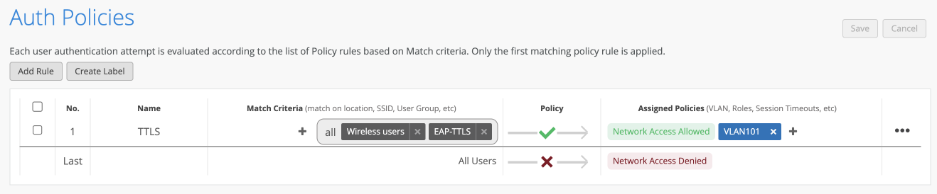
Create an Auth Policy:
Below is a screenshot of the Auth Policy I created. This policy will allow network access on VLAN 101 to any user who is in the “wireless users” AD group who has success completed EAT_TLS authentication. Everyone else is denied network access.
The Auth Policy UI is similar to the WXLAN policy IU and therefore existing Mist administrators should feel comfortable with the configuration of Auth Policies.
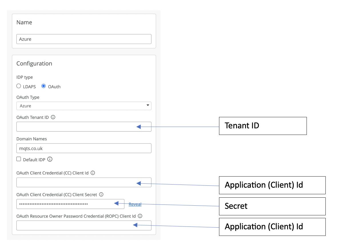
Setup an Identify Provider:
For the Identity provider I used Microsoft Azure AD. Integration with Azure AD requires three pieces of information:
1. Tenant ID – This can be found on your Azue AD overview page. to create an APP requestion for Mist
2. Application (Client) Id – You will need to create a new App registration for Mist, which will generate the Application (Client) ID for you.
3. Secret – Within you new App registration you will need to create a new secret under “Certificates and secrets”.
Once you have these pieces of information you can then configure the identify provider in Mist. Here is how the Mist fields map to the Azure information you have collected.
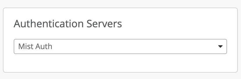
SSID configuration:
The final part of the configuration is to configure an 802.1X SSID with the Authentication Servers set to Mist Auth.
Cloud NAC concerns
Cloud-based NAC feels like a natural progression in a cloud-managed WLAN world. However, lets first look at two concerns cloud NAC raises.
First cloud NAC solutions go against the traditional advice of keeping your authentication server local to the user, to minimise latency especially for roaming Wi-Fi users. While this may have been a valid concern a number of years ago, today most enterprises implement some sort of centralised NAC solution, such as Cisco ISE or Aruba ClearPass instead of deploying distributed local RADIUS servers. This architecture is possible due to modern-day fast secure roaming protocols such as those defined by 802.11r, where authentication only happens on the initial connection to the network and cached keys are used when roaming between access points. Therefore, cloud NAC solutions implement alongside fast roaming protocols should provide a viable solution.
The second concern cloud-based NAC solution raise is: What if we loss internet connectivity? This is a bigger question then just NAC? A lot of organisations are now implementing a cloud first policy. As our workforces have become increasing mobile and work from home is the new norm having access to our office applications, email and data storage from any location just makes sense. So if all your data and applications are in the cloud, what happens when you lose internet connectivity? Authenticating new users will most likely not be your biggest issue. For the modern-day enterprise with a cloud-first focus maintaining a redundant, high-speed internet connection is critical to their business operations and NAC will be just one of many services with rely upon that availability.
That said a cloud NAC solution is not necessarily the right fit for all. For a variety of reasons some organisations prefer on-premise solutions and for these organisations a cloud NAC solitons would probably not be right choice.
Performance
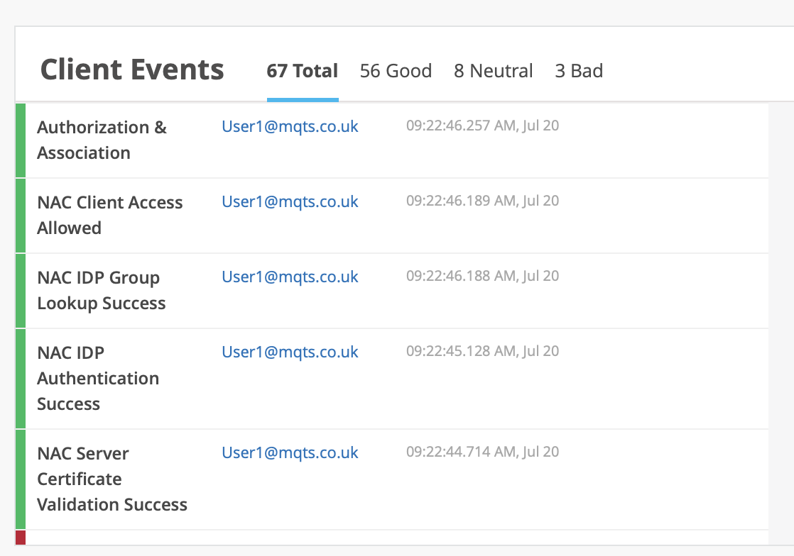
When analysing the performance of a user authentication using Mist NAC and Aruzre AD. I found the total 802.1X authentication could take as long as 2.3 seconds. However further investigation found that most of this time was the Azure AD lookups as see in the events below:
When using certificate-based authentication without the need for a third-party identity provider the Authentication times where greatly improved.
These longer authentication times mean the implementation of fast roaming protocols will be essential when using a cloud NAC solution.
Conclusions
Juniper Mist have done an excellent job in providing a powerful cloud-based NAC solution without the complex configurations which some more traditional NAC solutions suffer from. The Mist team have also done a great job ensuring UI constancy between the Auth Policy configuration and the WXLAN Policy configuration so the configuration should feel familiar to existing Mist Administrators.
The time of a cloud-based NAC 802.1X authentication will vary depending upon the EAP method and third-party identity provider selected. However, these times will generally be longer than using a local authentication server and therefore the deployment of a fast secure roaming protocol such as 802.11r will be essential for a success deployment.
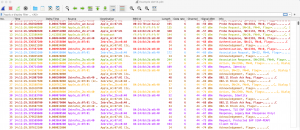
As many people know my preferred protocol analyser is LiveAction OmniPeek. However, I still find times when I need to run Wireshark, for example on my new MacBook M1 Max where running a windows application is not an option. So to make me feel more at home in Wireshark I have a created a colour profile for wireless analysis using OmniPeek colours.
In
Nov I sat Keith Parsons’s excellent ECSE Troubleshooting class. If you have not
already taken this class I would highly recommend it along with the ESCE Design
and ECSE Advance classes. During this class Keith was once again singing the
praises of Adrian Granados’ WLAN tools for MAC, in particular, on this class
the WiFi Signal tool. While giving praise and kudos to an awesome tool, Keith
also lamented those of us who are poor Windows users who don’t have such a
great tool and can’t easily access information about our current WLAN
connection. In defence of the “poor Windows users” I tried to point out that we
do have the ‘netsh wlan show interface’ command and you could script something
similar. However, I realised that this was a weak argument because I didn’t
possess a script to do this. So I decided write one.
Nigel
Bowden had written a script to write WLAN netsh information to a file:
So I
used Nigel’s script as a starting point and added a windows GUI and a few other
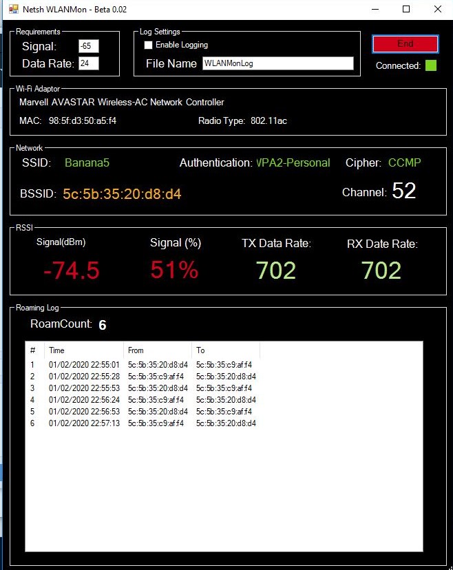
bits and finally arrived at my PowerShell NetSh WLAN Monitor Script
This
script provides the following features and functionality
A
Windows GUI to continually monitor the output from the ‘netsh wlan show
interface’ command
Configurable
signal strength and data rate thresholds allow the users to control the levels
at which the current signal strength and data rates will be disabled in green
or red text.
An
optional log – When logging is enabled, the output from each instance of the
‘netsh wlan show interface’ command will be written to a comma separated csv
file in ASCII format so it can be easily opened by tools such as Excel.
A
roaming log showing each roam.
By
default Windows restricts the execution of Powershell scripts, so you will need
to update the execution policy on your machine. To do this open a Powershell
window and temporarily set the policy to unrestricted with this command:
Set-ExecutionPolicy
Unrestricted -scope Process
Please
note the first version of the script is still beta, so let me know about any
bugs. But also let me know if you like it, should I continued to develop it? Some
of the things I hope to add soon:
MAC
OUI lookup
AP
name lookup
Other
WLAN metrics, such as MCS
Log
configuration
While
this script is no comparison to a professional tool such as Adrian’s WiFi
Signal, I hope many of you will still find it useful. The script can be
download here:
I hope you have fun with it, let me know your comments.
Note: This scripts only works for English windows systems and doesn’t work for other languages. I will look at updating this for other languages soon. Thanks Helge Magnus Keck for pointing this out.
This blog details an analysis of the packet capture capabilities of the WLAN Pi and seek to answer the question:- “can it be used to capture four 20MHz channels simultaneously?”. But before we delve into the detail, let’s start with some background and acknowledgments. The WLAN Pi is a WLAN testing tool built upon the NanoPi Neo2 single-board-computer (SBC) and has been developed by Jerry Olla – for more information please visit www.wlanpi.com. With the recommended Comfast CF-912AC Adapter, a user of the WLAN Pi can perform wireless packet capture.
Nigel Bowden developed a bat file called WLANPiShark which configures the WLAN Pi to be used as a TCP dump adapter to stream frames directly in to WireShark (See Nigel’s blog here).
Following Nigel’s blog, Gjermund Raaen wrote a blog article (here) describing how he was able to capture four 20MHz channels by using the WLAN Pi and WLANPiShark configured for one 80MHz wide capture channel. An obvious initial reaction to Gjermund’s blog was to point out that it is not possible to simultaneously capture on four 20MHz channels from one adapter. Gjermund was kind enough to share his capture files and very quickly it could be confirmed that he had in fact captured packets on all four 20MHz channels, within a single 80MHz channel, with very little packet loss.
A lab was therefore set up to try and understand the capabilities of the WLAN Pi packet capture solution and how the NIC’s 80MHz monitor mode was actually working.
How an 802.11 NIC configured for 80MHz channels receives data
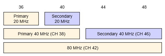
Before we go any further, it is important to understand how an 802.11ac NIC receives packets. 802.11ac 80MHz channels are composed of two 40MHz channels, bonded together. Each 40MHz channel is the product of two 20MHz channels bonded together. When APs are configured to operate on 80MHz channels, primary 40MHz and 20MHz channels are selected. When an 80MHz AP needs to talk to STA’s (stations) using 20MHz or 40MHz transmissions, it will usually transmit these on its primary channels. Figure 1 below illustrates an example of an 80MHz channel and its primary 20MHz and 40MHz channels.
Figure 1: Example 80MHz channel
When an 802.11 STA is operating on an 80MHz channel, it will listen on its primary 20MHz channel for PHY (physical) layer preambles and headers. 5GHz PHY preamble and headers are always transmitted on a 20MHz channel at 6Mbps using BPSK modulation. Information within the PHY header informs the STA how to receive the pending MAC frame – which includes the channel width, MCS, number of spatial streams and whether or not to use a short guard interval. Following the PHY header, the receiver will switch channel width, modulation, etc in order to receive the MAC frame.
After receiving the MAC frame, an STA will look at the receiver and BSSID MAC address to determine if it needs to pass this frame up the protocol stack.
How protocol analysers receive frames
As many will know, a popular protocol analyser is LiveAction’s Omnipeek. When fitted with the OmniWiFi adapter in monitor mode, Omnipeek receives frames in the same manner that a standard 802.11 STA does … with one exception. Although it listens on the configured primary 20MHz channel for PHY headers to know how to receive an imminent MAC frame, in monitor mode the adapter will pass all MAC frames up the stack to the analyser regardless of the frame’s MAC addresses. Therefore, if we configure our analyser to capture 802.11ac primary CH36, as indicated in Figure 1, our capture would receive all frames transmitted on the configured 80MHz, primary 40MHz and primary 20MHz channels. However, it would not receive frames transmitted on the secondary 20MHz or 40MHz channels because their PHY headers would not be transmitted on CH36.
Why is the WLAN Pi packet capture different?
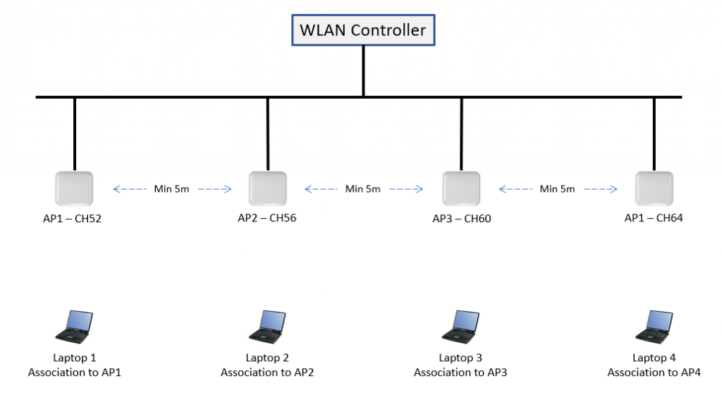
To investigate how the WLAN Pi was performing an 80MHz packet capture, the lab environment shown in Figure 2 was setup and the WLAN Pi was configured as a TCP dump adapter into Omnipeek The WLAN Pi’s Comfast CF-912AC Adapter was set to CH52 80MHz.
Figure 2: Lab network
Test 1 – Ping
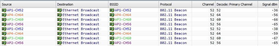
For the first test, a continuous Ping to WLAN controller was sent from each laptop. Initial analysis of the beacon frames captured showed that beacons were being captured from each of the lab APs. In Figure 3 you can see the beacon frames. Notice the capture channel is set to Channel 52 for all frames, but the channel on which the Beacons were transmitted is shown in the “Decode: Primary Channel” column.
Figure 3: Beacon Frames in Ping test
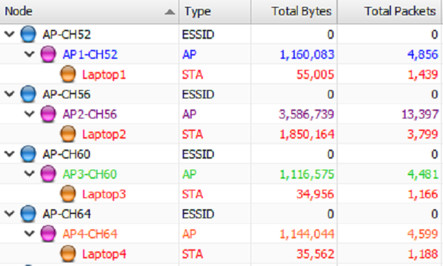
If we look at the WLAN statistics, we can see that we have captured frames from all four APs and their associated laptops.
Figure 4: Packet and Byte statistics from Ping test
However, taking a closer look at these statistics, we notice that far more packets have been captured on channel 56 than for the other channels. Further investigations revealed that, although we captured most of the packets transmitted by Laptop 2, most of the packets captured from Laptops 1, 3 and 4 were mainly control, management and broadcast data frames with the majority of the unicast data frames absent.
Why was the WLAN Pi adapter favouring channel 56? The primary capture channel was changed to channel 64; but the WLAN Pi adapter still favoured data from channel 56. Power cycling the WLAN Pi had no effect on this behaviour.
Test 2 – Throughput.
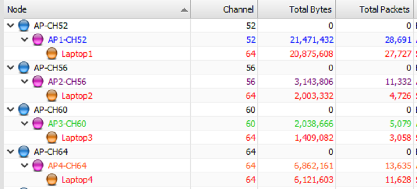
For the second test a large download was initiated on each laptop. This time the capture was configured on channel 64 with an 80MHz channel width. The results were similar to those from the ping test but this time channel 52 was the favoured channel and the difference between the volume of packets captured for each channel was much clearer.
Figure 5: Packet and Byte statistics from Throughput test
From this test, it was clear that while the WLAN Pi’s adapter was tied up capturing a frame on one 20MHz channel it was not able to simultaneously capture frames on the other 20MHz channels across the same 80MHz channel.
Conclusions
When configuring the WLAN Pi with a Comfast CF-912AC adapter in Monitor mode with an 80MHz channel width, the following conclusions were drawn:
The adapter will listen for PHY preamble and headers on all individual 20MHz channels within an 80MHz channel. Whether or not it does this simultaneously or cycles though these is unclear from this testing.
The adapter is not able to capture frame transmissions on two 20MHz channels simultaneously. While it is receiving a frame on one 20MHz channel it will ignore the other 20MHz channels within the same 80MHz channel.
The adapter will favour one of the 20MHz channels during capture. A way was not found for predicting which channel will be favoured. Therefore, this 80MHz capture solution is unusable for detailed analysis and troubleshooting work, as there is no way to guarantee you will capture on the channel you require. The recommendation is to only select 20MHz channel captures with the WLAN Pi if you want to guarantee a valid 20MHz captures.
While the WLAN Pi is not going to replace the packet capture tool kit yet, the 80MHz monitor mode of the CF-912 is interesting. Perhaps if there could be more control over its behaviour, there may turn out to be some valid use cases.
The original 802.11 standard supported two authentication methods: open system and shared key. The publication of the 802.11r amendment added a third authentication method call FT Authentication. Now that support for 802.11r is available for both clients and WLAN infrastructure, this article will explore the protocol exchange used to perform Over the Air FT (FastTransition) authentication. This article assumes a familiarity with 802.11 protocols, knowledge of 802.1x authentication, the 4 way Handshake, Pairwise Master Key (PMK) and Pairwise Transient Key (PTK).
Every 802.11 station joining a BSS (Basic Service Set) must first perform 802.11 authentication (this is not to be confused with 802.1x/EAP authentication which takes place following the station’s association). The IEEE 802.11-2012 Standard defines four different authentication methods:
OpenSystem– No Authentication, everyone is allowed
SharedKey – Authenticates stations using WEPto demonstrate knowledge of a configured WEP key
FastTransition (FT)– Introduced to the 802.11 standard by the 802.11r amendment. Authentication relies upon a key derived from previous authentication. Used to facilitate fast BSS transition for roaming 802.1x stations.
Simultaneousauthentication of equals (SAE) – Introduced to the 802.11 standard by the802.11s amendment. Uses finite field cryptography to prove knowledge of ashared password. Based on the Diffie-Hellman key exchange.
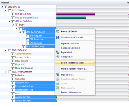
This blog article focuses on FT authentication and howthe FT authentication differs from other Fast Secure Roaming Protocols. Thescreens shots and decodes shown are taken from a recent lab exercised I performed to capture and analyse the FT authentication process.
Lab Setup
This lab was performed using an iPhone roaming between two Motorola/Zebra AP-7532s connected to an RFS4000 WLAN controller. All packets were capture using WildPackets’ OmniPeek. For readability, all traces files have been filtered to only show the following frames types:- Authentication, Association Request, Association Response, Re-association Request, Re-association Response and 802.1x/EAP frames, as shown below.
Pre 802.11r Fast Roaming
PMK Caching, Pre-Authentication and Opportunistic Key Caching (OKC) are all fast secure roaming methods adopted pre the publication of 802.11r amendment. Each of these methods removed the need for an 802.1x client to perform a full 802.1x\EAP authentication when they roam between BSSs. This is achieved by the client and wireless infrastructure caching the Pairwise Master Key (PMK) from a previous association. After performing a successful Authentication and Reassociation, the client may then use its cached PMK to perform the Four-Way Handshake. This process can be seen in the figure below, the packets show a client’s initial full authentication to a BSS followed by the client’s roam and Reassociation to the second AP.
Notice that following the client’s Reassociation, it proceeds straight to the four-way key exchange.
FT
FT protocols are part of the Reassociation service and only apply to a station that transitions between APs. FT protocol messages can be exchanged by one of two methods:
1. Over the Air – Communicated directly with the target AP using FT authentication
2. Over the DS – Communicated with the target AP via the current AP.
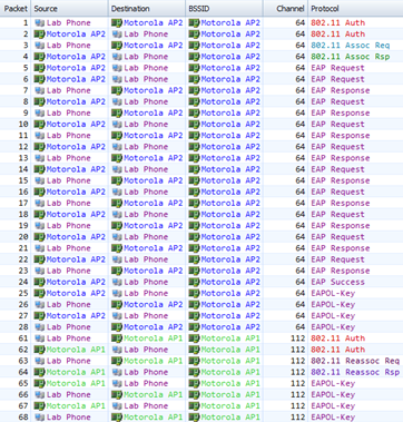
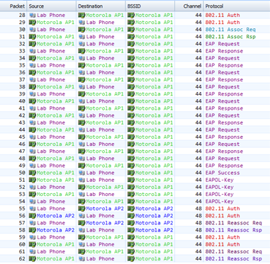
In this blog we will explore the Over the Air protocol exchange, which utilises FT Authentication. When Over the Air Reassociation is used, a roaming station only needs to perform Authentication and Reassociation, as the functions of the Four-Way Handshake are incorporated into the FT authentication and reassociation frames. The packets below show the initial association by the client (Open System authentication , Association, 802.1x EAP authentication and the 4 Way Handshake) following by two FT roams (FT Authentication & Reassocation).
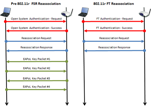
Notice the lack of a 4 Way Handshake. This process is now embedded into the Authentication and Reassocation frames. The figure below compares pre 802.11r fast roaming and FT Roaming
FT Key Hierarchy
Before we explore the FT Authentication and Reassocation packets in more detail, first we need to understand a bit of background on the FT Key Hierarchy.
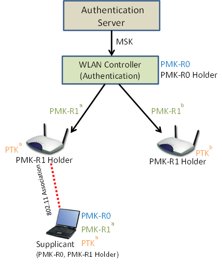
For this explanation I will assume a controller–based WLAN architecture, where the controller is the 802.1x authenticator. This environment matches my lab environment and is shown in the figure below.
A three-level key hierarchy is used to support fast BSS transition consisting of the following keys:
PMK-R0 – First level key – Key is derived as a function of the Master Session Key (MSK)
PMK-R1 – Second level key – Key is derived mutually by holders of PMK-R0
PTK – Third level key – this key defines protection keys and is derived mutually by holders of the PMK-R1
The Master Session Key is derived simultaneously by the Supplicant and Authentication Server via the 802.1x authentication process. Following a station’s initial full 802.1x authentication to an ESS, the Master Session Key is passed from the Authentication Server to the Authenticator encrypted in the RADIUS shared secret. These two processes result in both Supplicant and Authenticator holding the MSK. Both Supplicant and Authenticator can subsequently derive the PMK-R0 and the Authenticator becomes a PMK-R0 holder (in our example shown above this is the WLAN controller).
The authenticator will use the PMK-R0 to derive a PMK-R1 for the individual access point the supplicant is associated to. Subsequently the authenticator can then derive and send individual PMK-R1 keys to access points to which the supplicant may subsequently roam. The supplicant derives a PMK-R1 for the BSS to which to it will (re)associate from a standardised function utilising its cached copy of PMK-R0 and the BSSID.
Following this process the supplicant will perform a four-way handshake with the initial AP to form a security association and derive the PTK. When roaming to a new access point, only FT Authentication and Reassocation is required to form the security association and derive the PTK.
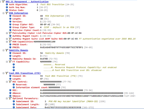
Packet 1: Authentication Frame
The first Authentication frame is sent by the client to the AP, see decode below:
Notice the Authentication Algorithm is set to 2 – indicating that this is an FT Authentication and not Open System Authentication. In the Authentication Management Suite list of the RSN Information element, we can see that the client has chosen FT authentication (OUI 00-0F-AC-03). Also in the RSN Information element, we find the PMKID list – which holds a list of IDs for the PMKs that the client believes to be valid for the destination AP. In the Fast BSS Transition (FTE) element, we see the SNonce (Supplicant Nonce) being transmitted along with a PMK-R0 key holder ID. In a non-FT roam, the SNonce would have been transmitted in the second packet of the four-way handshake.
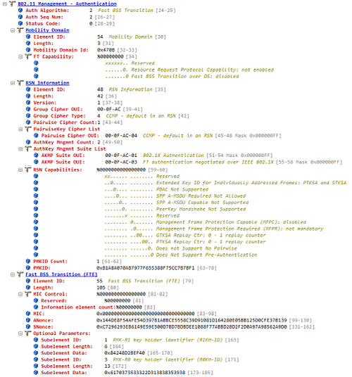
Packet 2: Authentication Frame
The next FT Authentication frame is from the AP to the client and is show below:
In the second FT Authentication frame the ANonce is included in the Fast BSS Transaction element. This would have been communicated in the first EAPoL Key packet of the Four-Way Handshake. The Fast BSS Transaction element also includes the PMK-R1 key holder ID.
At this point both the supplicant (Client) and Authenticator (WLAN infrastructure) have the information needed to generated, a Pairwise Transient Key (PTK):
Now let’s look at the Fast BSS Transition element (FTE) in the Reassociation Request frame:
The ANonce, SNonce, R0KH-ID and R1KH-ID are set to the values contained in the last Authentication frame. In this frame, a Message Integrity Code (MIC) is calculated using the newly derived PTK. The PTK is actually a concatenation of a number of session keys. One of these session keys, the Key Confirmation Key (KCK) is used along with the AES-128-CMAC algorithm to calculate the MIC
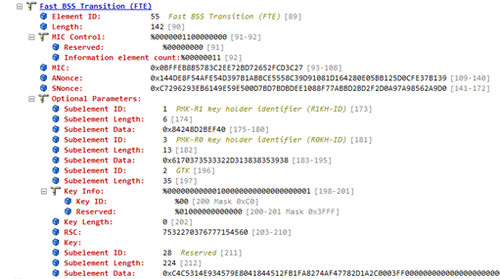
Packet 4: Reassociation Response Frame
The last frame in the four-way FT exchange is the Association Response frame. The FTE from the Association response frame is shown below:
The ANonce, SNonce, R0KH-ID and R1KH-ID are set to the values contained in the Association Request frame. This frame also includes a MIC calculated in the same way as the MIC in the Association request frames.
You will notice some key info is also transmitted in the optional parameters of this frame. This is the Group Temporal Key (GTK), used to protect broadcast and multicast frames. This Key is encrypted in another PTK session key called the Key Encryption Key (KEK).
The result of this process is that the supplicant’s authentication has been verified through its possession of a valid PMK and a new PTK has been derived on the supplicant and authenticator. The client has also been provided with the current GTK for the BSS.
Despite the title of this blog, this is a not a “beat-up” on Aruba, and the questions I ask in this blog I would encourage you to ask of any Vendor’s onboarding solution, I pick Aruba as an example only.
I would like to start with a given: SSL Man-In-The-Middle Attacks via open public wireless networks are very easy to carry out with tools that are freely available on the internet. If this is news to you then see the link below. I will not be discussing the details of this attack in this blog.
Lets’ begin with the problems onboarding strives to fix: How do my employees connect to the corporate secure network on their personal devices, without occurring a significant administration and helpdesk overhead. 802.1x with EAP methods such TLS and PEAP have allowed corporately owned devices to connect securely to the network for a number of years. These methods bring with them a number of challenges such complex client configurations and the provisioning of digital certificates to the client devices. For corporate owned and managed devices these challenges can be overcome though a variety of methods, which lock down the wireless setting on the clients device with configuration changes and new certificates being pushed out though AD group policy or via an MDM solution.
When it comes to BYOD, getting certificates and the correct 802.1x configuration onto employee owned devices is a challenge that onboarding seeks to address through an automatic configuration process, without the involvement of the IT team.
Aruba’s ClearPass supports two onboarding methods: using two SSIDs or using a single SSID. I will take these two methods in turn.
Two SSIDS
An open SSID is used as a provisioning SSID, for initial connections. Employee’s would initially connect to this SSID and be redirected to a web portal where they would enter their AD credentials. Once authenticated the users will be prompted to download a small utility which will install certificates and configure the employee’s device to connect to a second secure SSID, on Apple ISO devices this process can be done over air without the installation of the configuration utility. Once configured the employees will connect to the secure SSID and be able to access the required network resources.
My concern with this method is: what is protecting the user’s AD credentials which are exchanged over the open SSID? The answer is that if the web portal is using HTTPS then it is SSL. As has already been stated at the beginning of the article, it is easy to perform an SSL Man-in-the-middle attack on an open SSID, by impersonating the provisioning SSID and hi-jacking authorised users. This attack will expose the users AD credentials to the attacker.
One SSID
Aruba also provides an alternative method where the same secure SSID is used for provisioning and access. With this method users can connect to the SSID using WPA2 802.1x/PEAP authentication using their AD credentials, they will then have their device provisioned for 802.1x/TLS connection to the same SSID. After provisioning they will connect using TLS certificate authentication. Although this option protects against the SSL Man-in-the-middle attacks highlighted above, it seems to nullify the benefits of using onboarding in the first place. When using PEAP you still need to provision the server-side certificate to the users, although this could be dealt with through the purchased of a certificate from a public certificate authority. Secondly you need the user to successfully configure their device for PEAP, ensuring they validate the service-side certificate, and not exposing them to a layer 2 man-in-the-middle attack.
Closing Remarks
I hope this article will encourage people to think about and question the systems they implement and to that end I close with the following questions and comments:
What about using WPA2-PSK for BYOD? If PSK is compromised an attacker could get access to your wireless network- Is this better or worse then your AD credentials being compromised? Once a PSK is compromised user traffic can be decrypted in real time potentially providing an attacker access to user’s AD credentials. Could using a PSK for the provisioning SSID be a nice compromise?
Can you detect/protect against wireless man-in-the-middle attacks? A good Wireless IDS system will be able to detect and in some cases protect against a wireless hi-jacking attack (the first step to compromising onboarding using an open SSID). It would therefore be recommended to consider an enterprise class WISP as part of an onboarding implementation.
Where does the future of 802.11 packet capture lie?
We are very familiar with performing 802.11 packet capture using USB wireless dongles as capture adaptors. The problem with USB adaptors is that they can only support up to 2 spatial streams due to limitations of the USB bus. With the advent of 3+ spatial streams APs, these USB dongles are no longer adequate capture adaptors. At the Wireless LAN Professionals Summit 2014, Jay Botelho, Director of Product Management, WildPackets, said that he sees capturing from access points as the future of 802.11 packet analysis. Capturing packets from an installed access point can provide an excellent approach for remote troubleshooting. But how about using an access point as a capture adapter connected directly to your laptop? Below I will show a procedure I used for capturing packets directly from an Aruba IAP-225 into WildPackets OmniPeek.
Setup
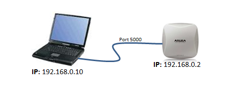
In the following example I have an Aruba IAP-225 running 6.3.1.0-4.0.0.0 connected directly to my laptop via an Ethernet cable. On my laptop I’m running OmniPeek version 7.9.1.
You will need to make sure you have configured an IP address on both the IAP-225 and your laptop. Test you have basic IP connectivity by pinging the access point from your laptop.
Procedure
Currently packet capture on Aruba Instant APs can only be configured from the cli. So you will need to SSH or Console to the access point.
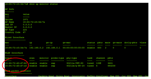
1) First we need to determine the BSSID of the radio we are would like to capture on. To do this we type the command: show ap monitor status . This command will display a whole wealth of information on the access point, but for this task we are only interested in the BSSID information shown in the figure below. We will see both the 2.4GHz and 5 GHz radio BSSIDs. Copy the BSSID for the radio you wish to capture from. For this example I’m going to use the 2.4GHz radio 18:64:72:d3:d7:a0
2) To start a packet capture on an Aruba IAP we use the following command:
In this example I’m going to capture from the 2.4Ghz radio 18:64:72:d3:d7:a0. The IP address of my laptop running OmniPeek is 192.168.0.10. I’m going to use port 5000, but you could use any port.
The format parameter is a number indicating the packet format. This allows you to send the packets in the correct format for the analyser of your choice. In this example I’m using WildPackets OmniPeek, but options for analysis such as Wireshark or AirMagnet exist. The different options for this parameter are shown below:
0 pcap, 1 peek, 2 airmagnet, 3 pcap radio, 4 ppi
Because I’m using OmniPeek I will choose 1 for peek format.
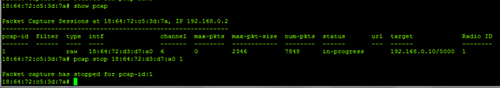
The last parameter is the maximum packet size, for this example I’m going to use a value of 2346. So for my example setup I would type:
Notice the pcap-id is shown in the resulting message (see above). This id will be used when we issue the command to stop the capture. If you want the access point to capture both 2.4GHz and 5GHz traffic simultaneously then issue the pacp start command again but this time use the 5GHz radio BSSID.
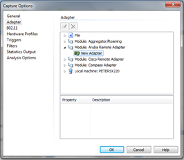
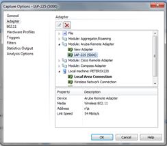
3) Next we need to start an Aruba Remote Adopter capture in OmniPeek. In OmniPeek select the ‘New Capture’ option from the Start Page. The Capture Options dialog will appear, on the Adapter tab choose ‘Aruba Remote Adapter’ and double click ‘New Adapter’
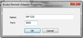
Enter a name and the port number. In this example I’m using port 5000. Click ok.
Make sure your newly created Aruba adapter is selected and click ok
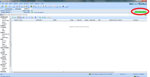
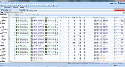
When the capture window opens click ‘Start Aruba Capture’
Your packets should now start to appear. Happy Analysis!
4) When you have finished capturing remember to stop the capture on the access point.
pcap stop 18:64:72:d3:d7:a0 1
In this command the digit 1 is the pcap id, this was displayed when I started the capture. If you can’t remember the pcap id then you can use the command show pcap to see your current captures.
If you started a capture from the 5 GHz radio, then you will need to stop this one too.